

CCC IOC-555-D Precision Timer/Counter Integrated Circuit
- Product Code: CCC IOC-555-D
- Availability: In Stock
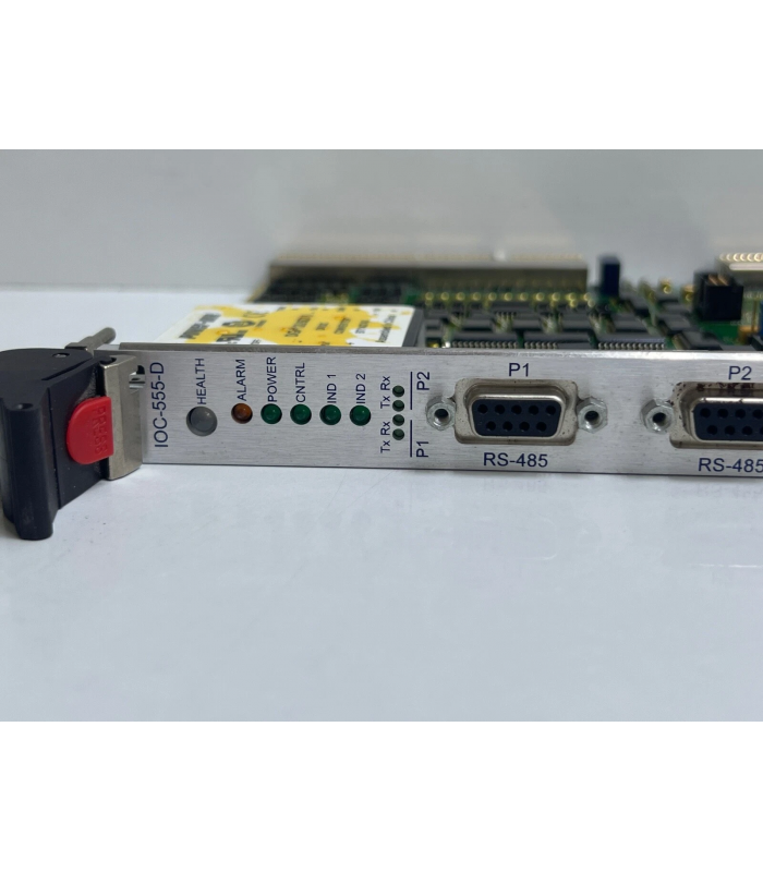
CCC IOC-555-D
Precision Timer/Counter Integrated Circuit
General Specifications
| Parameter | Value | Description |
| Supply Voltage Range | 4.5V to 16V DC | Operating voltage range |
| Operating Temperature | -40°C to 105°C | Industrial temperature range |
| Output Current | 200mA (max) | Source or sink capability |
| Timing Range | Microseconds to hours | Adjustable via external components |
| Power Consumption | 3mA (typical @ 5V) | Quiescent current |
| Package Type | 8-pin DIP/SOIC | Dual In-line Package/Small Outline IC |
Pin Configuration
| Pin Number | Name | Function Description |
| 1 | GND | Ground (0V) connection |
| 2 | TRIG | Trigger input: activates timing cycle when voltage falls below 1/3 VCC |
| 3 | OUT | Output pin: provides high or low signal (sinks/sources up to 200mA) |
| 4 | RESET | Reset input: active low, resets timer when pulled below 0.8V |
| 5 | CTRL | Control voltage: adjusts threshold levels (normally bypassed with 0.01µF capacitor) |
| 6 | THRESH | Threshold input: resets output when voltage exceeds 2/3 VCC |
| 7 | DISCH | Discharge: provides discharge path for external capacitor |
| 8 | VCC | Positive power supply (4.5V to 16V) |
Functional Description
The CCC IOC-555-D is a highly stable integrated circuit designed for generating accurate time delays or oscillation. It consists of two voltage comparators, an RS flip-flop, a discharge transistor, and a resistor divider network.
The threshold and trigger levels are normally two-thirds and one-third of VCC, respectively. These levels can be altered by using the control-voltage terminal (pin 5). When the trigger input (pin 2) falls below the trigger level, the flip-flop is set, and the output (pin 3) goes high. If the trigger input is above the trigger level and the threshold input (pin 6) is above the threshold level, the flip-flop is reset and the output is low.
Operating Modes
1. Astable Mode (Free-Running Oscillator)
In this mode, the device operates as a free-running oscillator without external triggering. The frequency and duty cycle are determined by two external resistors (R1, R2) and one capacitor (C1):
- High time: tH = 0.693 × C1 × (R1 + R2)
- Low time: tL = 0.693 × C1 × R2
- Frequency: f = 1 / (tH + tL) = 1.44 / (C1 × (R1 + 2R2))
- Duty cycle: % = (R1 + R2) / (R1 + 2R2) × 100
2. Monostable Mode (One-Shot)
In this mode, the device produces a single fixed-duration output pulse in response to an external trigger. The pulse width is determined by one external resistor (R) and one capacitor (C):
- Pulse width: t = 1.1 × R × C
- Trigger voltage: < 1/3 VCC
- Trigger pulse width: > 0.1µs
3. Bistable Mode (Flip-Flop)
In this mode, the device functions as a basic flip-flop or Schmitt trigger without external timing components:
- Set (output high): Trigger pin (2) < 1/3 VCC
- Reset (output low): Reset pin (4) < 0.8V
- Hysteresis: 1/3 VCC (between 1/3 and 2/3 VCC)
Typical Applications
- Pulse generation and timing circuits
- LED flashers and beeper circuits
- Pulse width modulation (PWM)
- Frequency division and counting
- Time delay circuits and timers
- Schmitt trigger and flip-flop circuits
- Tone generation and audio circuits
- Instrumentation and measurement equipment
© 2025 CCC Electronics Corporation. All rights reserved.
Document No.: IOC-555-D-DS-001 Rev. A